

Media


News
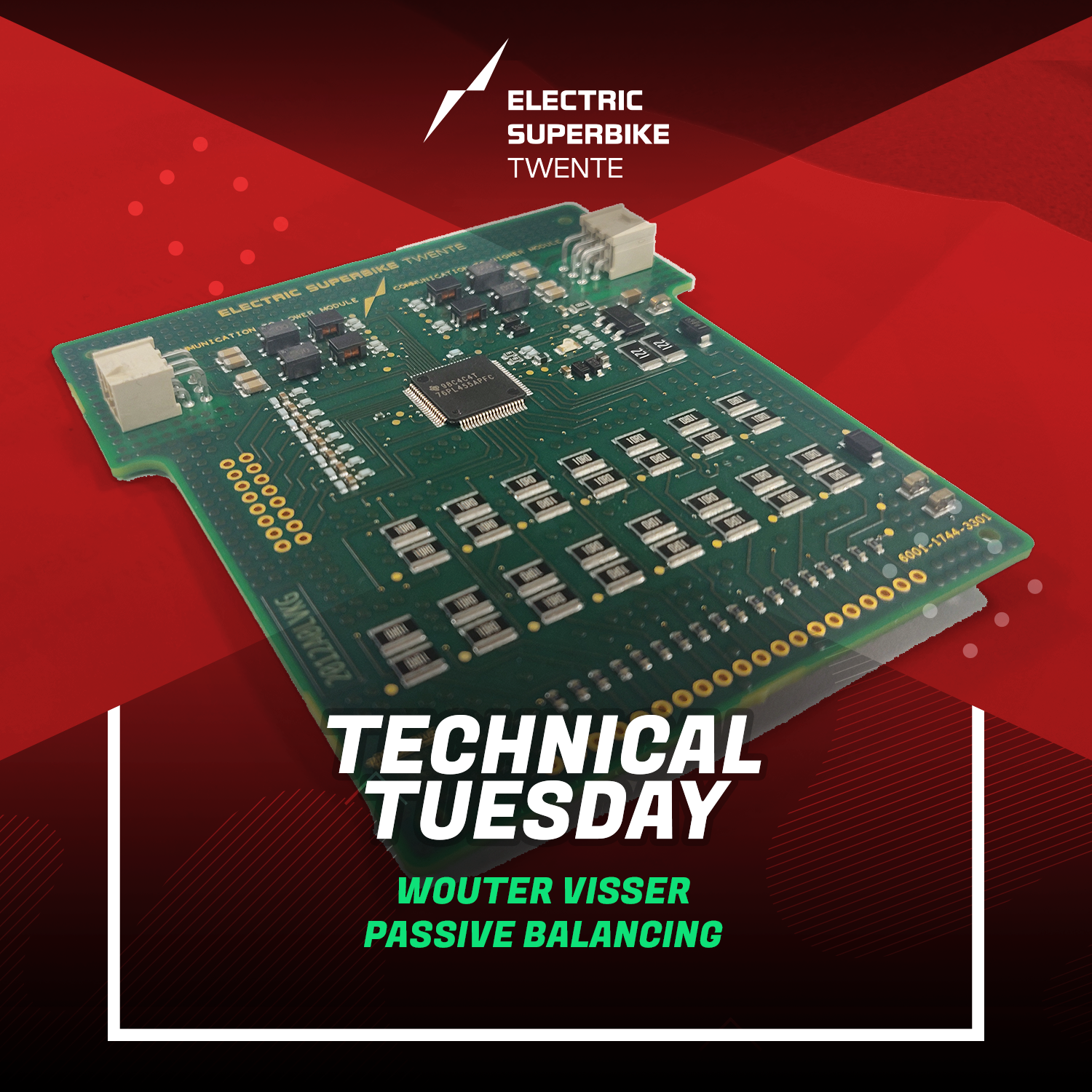
Technical Tuesday: Passive Balancing
In order to make sure we have enough capacity in our battery pack to go racing, it has to consist of multiple cells. However, all these cells need to be managed. To this end, the battery pack is split up into 12 different parts, known as the modules. Each of these modules in turn is made up of 16 groups of 3 battery cells, and equipped with a chip to manage the module, called the BQ chip.
The problem is that these cells all discharge at a different rate. This makes that, after a while, some cells are more full than others. When discharging, these different energy levels mean that you have to stop discharging when the cell with the lowest level is empty. The inverse is true for charging the battery, so the charging has to stop when the fullest cell is full. This means that you can’t make the best use of your battery pack, as most cells will not be filled entirely, and they also won’t be emptied entirely.
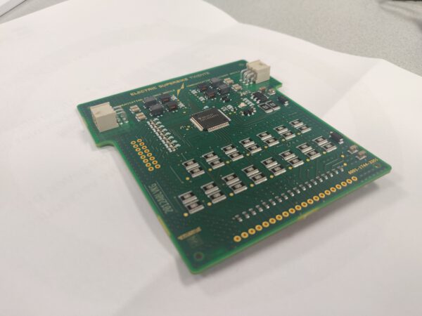
Because of this, the cells need to be balanced. This means making sure that all the cells have the same energy in them. We do this with a process called passive balancing. With passive balancing, you accomplish this by slowly discharging the cells that are too full. Then, when they are as full as the lowest capacity battery, you stop discharging that cell. Eventually, all cells will then be at the same level.
It was already possible for us to do this with the software included with the BQ chip. But now we have created a new tool that allows us to do this in a different and more efficient way. Firstly, the old software allowed us to balance only one module at a time. Because the balancing process takes quite a long time, this meant that one person had to spend a long time monitoring the battery pack, and it could not be used for this entire time. On top of this, the old software allowed the cells to be balanced to the minimum of the module it was in. This meant that the issue of different levels was still there, as the different modules are still discharged at different rates.
Our new tool solves both those issues, as it was created to monitor the entire battery pack and not just the modules. This way, all the cells can be balanced at the same time, and all to the same target. This means that we can get even more power from the battery pack and that we can race for an even longer time.
– Wouter Visser
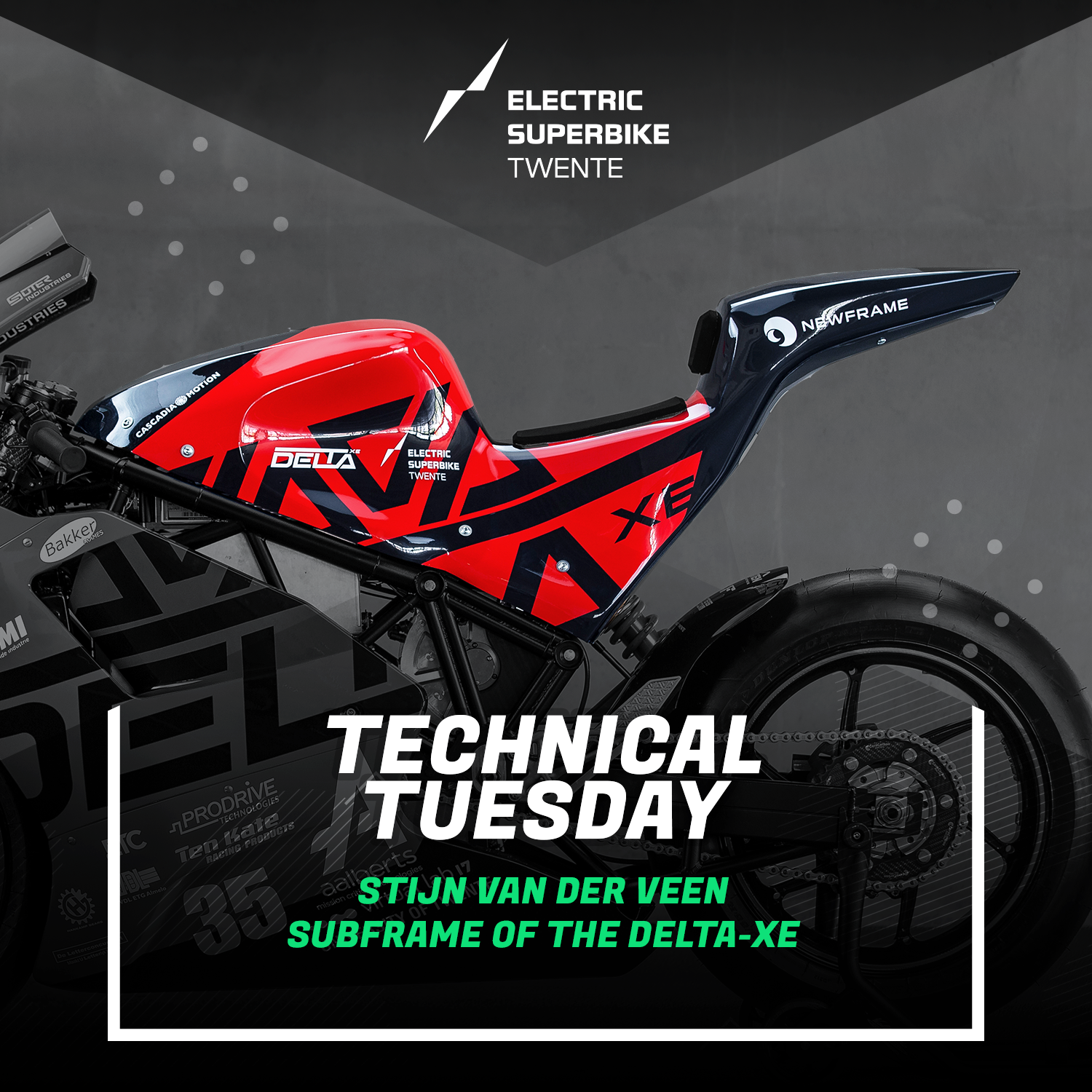
Technical Tuesday: Subframe of the DELTA-XE
The Delta XE is enveloped by bodywork that gives the bike a neat look and enhances the aerodynamic properties of the bike. The top part of the bodywork is called the subframe. The subframe is part of the frame, as it is mounted directly to it. The subframe should be able to handle the load of the rider while the motorcycle is on the track.
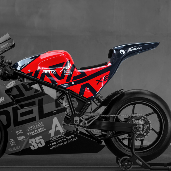
Currently, the subframe of the Delta is made out of a carbon fibre composite. In order to fabricate such a part, a mould is needed to shape the carbon sheets. A total of ten layers of carbon is used to give the subframe the strength and low weight it needs. A type of foam is used in the middle of these layers to enhance the strength.
The subframe is designed to protect the components that are located beneath it, such as the motor controller, from water and debris. Furthermore, it gives the rider a place to put his legs on, allowing him to clamp around the bike and maintain stability. Unfortunately, the space that should be occupied by the motor controller was limited by a torsion bar in the front of the motorcycle. This bar prevented the motor controller to be located in the front and instead of being placed underneath the bar, it was moved further back. However, the motor controller proved to be larger than expected, interfering with the subframe from the inside. This problem was solved by taking a small amount of material out of the subframe at the locations where the motor controller comes in contact with the subframe. Furthermore, the frame warped after welding, causing the mounting tabs for the subframe to be slightly misaligned. The subframe mounting holes do not match the mounting tabs of the frame as a result. This can be solved by using the current subframe as a template for the new subframe in order to determine the new locations of the mounting holes.
The fact that the current subframe has some imperfections allows us to tweak the design, making it better as a result. Firstly, the new design can be lighter. Fewer carbon sheets can be used to maintain sufficient strength, while reducing the weight significantly. Secondly, the subframe requires slightly more width at the locations where the motor controller interferes with the subframe. The mould of the current subframe has already been manufactured, and creating a new mould is rather expensive. This means that for a new subframe, with the changes mentioned above, the mould needs to be changed accordingly. It can be achieved by editing the mould file with CAD software after which a CNC router is able to determine toolpaths and adjust the mould as desired. This way the new mould can be used to manufacture a new subframe. Ultimately, this should give us a subframe that is both lighter, easier to attach and a better fit.
– Stijn van der Veen