For the communication between parts of our electric superbike we use a so-called CAN bus. Which stands for Controller Area Network. You can think of this bus like an actual city bus. It travels around the entire superbike (city), delivering the necessary information (people) to the receivers (bus stops). Different from an actual bus it the fact that in a CAN bus, the information is not lost after a bus stop. It gets back on the bus for the next receiver to read. In that way, all information sent on the CAN bus can be received by everyone that wants it.
The bus stops from the analogy above are representative of the CAN nodes in the superbike. These nodes can receive information from the CAN bus and can also put more information on the bus. The CAN nodes are connected to all kinds of sensors, like temperature and flow sensors, but also to the throttle. The nodes then perform the needed calculations to make sense of the sensor signals and then put it on the CAN bus for other nodes to use. 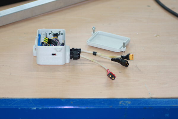
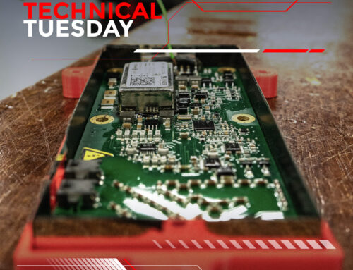
The nodes, designed by EST4.0, consist of several sections. To power everything a buck converter is used to convert 12V into 5V. A second section takes care of receiving and sending the CAN signals. The third section takes care of connecting all the sensors to the node. Finally, the brain of our CAN nodes consists of a Teensy 3.6 microcontroller. This takes care of all the calculations that need to be performed. While this system works, it is not ideal in terms of reliability, therefore, this year we want to replace the Teensy 3.6 with an automotive grade microcontroller.
The physical design of the CAN nodes consists of a multitude of things. The most obvious being the outside housing of everything. This provides the CAN nodes with protection from the elements. Secondly, the PCB is there to provide a base for and connect all the components. Third is the Teensy 3.6. And finally, the connectors that provide a connection to the rest of the superbike, like the power connectors and the CAN connector.
– Robin Venhuizen